MS4580 - AtoN A IS
For Information and Prices Contact Us
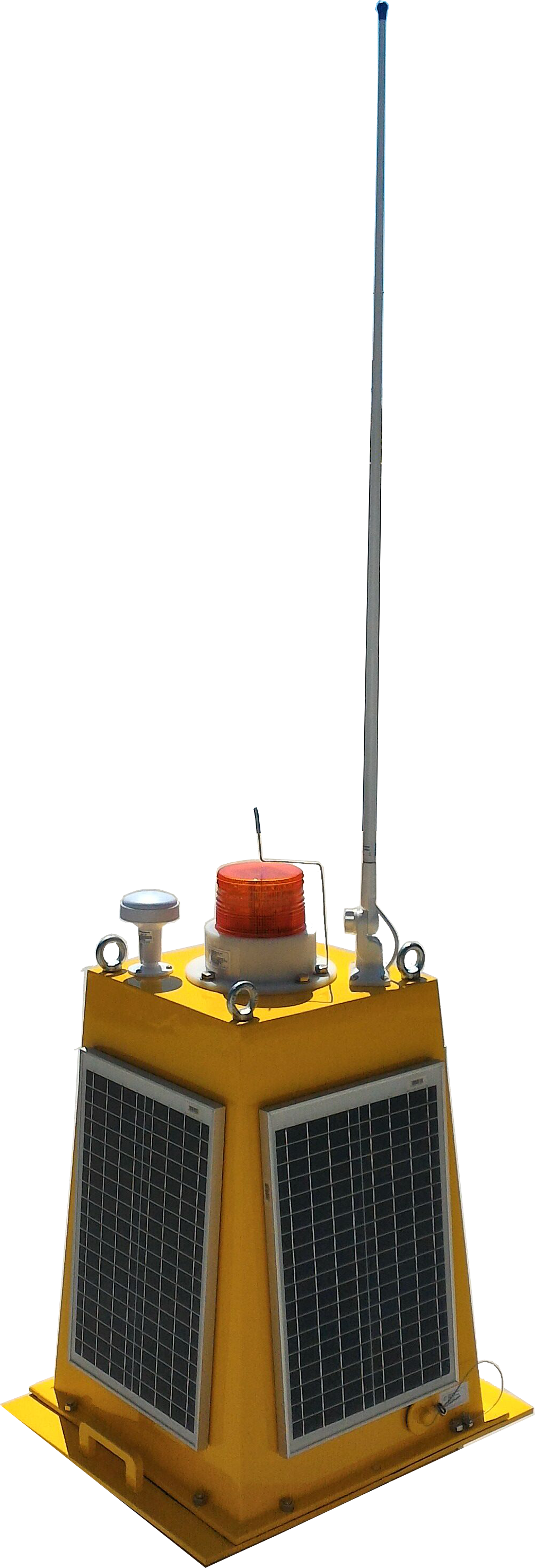
The MS4580 is a self-powered flashlight designed with state-of-the-art technologies to offer many possibilities and ease of communication integration through 10Base-T TPC / IP and Wifi type connections that allow full configuration through your Web server.
Its MS4510 or MS4515 flashlight allows applications ranging from 3 up to 10nm with 4w Super Bright LEDs in Red, Green, Blue and White (RGBW) with 360 ° horizontal and 5 ° vertical, intensity control with 256 flash settings , The most advanced microprocessor and Web server in the market for configurations.
The MS4580 module is a base equipped with a 80W solar power system with battery capacity of 115Ah for use of Flashlights (MS451X, not included), Optional Wind Instruments, Wind Direction, Temperature, Humidity, (Barometers, Gyroscope, Temperature Compass, Odometer, Depth, etc.), GSM Telemetry and allows the use of AtoN - AtoN - Aids AIS modules for Navigation Report, or "Navigation Assist" with messages established by ITUR M.1371 with messages 21, 6, 7, 8, 12, 13, 14, 25, as well as AtoN identity, AtoN type, And its position, this message also carries a digital flag to indicate if a floating AtoN is out of position. Message 21 will increasingly be an important part of navigation, which is being developed by the IMO (International Maritime Organization) and IALA. All units in these modules transmit the messages in a range that is configurable by the user.
AtoN Module Monitoring
ITU-R M.1371 defines Message 6 as an addressed binary message, used for sending data from one station to another AIS.
The module uses Message 6 to convey comprehensive information about the operational status of a flashlight, its power supply, and so on.
The AtoN authority may have its own monitoring center, or may assign the control task to a VTS - Vessel Traffic Services center or other existing facility. Whatever the location, the monitoring data of each AtoN AIS site can be easily transferred to the required point through the AIS network. Early warning of failures or failure of a flashlight or power supply allows the authority to respond quickly to maintenance by increasing the availability of the AtoN service.
Meteorological and hydrological report
Message 8 is defined by ITU-R M.1371 as a binary message to be transmitted, which means that it is intended for multiple users. The IMO (International Maritime Organization) has defined a version of Message 8 for the transport of meteorological and hydrological data. The module can transmit this message at set intervals during unit configuration.
External sensors are naturally required to obtain most of the meteorological and hydrological data, module can provide complete systems easily through its internal Ethernet structure that compatible with all TCP / IP-based family devices.
The module can measure wave height, period and direction using its internal operating system and its tilt and gyro sensors and add to the meteorological and hydrological messages (Wind speed, wind direction, air temperature, water temperature, air humidity, Relative humidity, barometer, magnetic compass, light intensity, rain gauge, etc.) for broadcasting, so no external sensor is required. The user should consider that wave precision can be affected by buoy movement.
Autonomous Solar Power Supply
The module provides its own autonomous power source for powering your system through 4 solar side cells, its charge controller and its fully sealed stationary battery mounted in its enclosure.
GPS / GLONASS
Optionally, the module can contain a 167-channel GPS / GLONASS, independent of a Flashlight, capable of receiving satellites of the American constellation (GPS) and Russian constellation (GLONASS) with excellent stability and accuracy of up to 2.5 meters.
GLONASS is the satellite navigation system that has been developed by Russia since 1976 and now has 24 satellites in orbit, which are responsible for providing positioning data.
With the end of the Soviet Union, the project was virtually abandoned, but over the last few years under Vladimir Putin, the restoration of the system was made with high priority, and GLONASS is now the most expensive program funded by the Russian Federal Space Agency , Costing about a third of its budget in 2010.
Its operation is very similar to the American GPS, because it has 24 satellites that are distributed between three layers with 8 satellites in each, and the position of the equipment is formed by at least 3 of them through a process called trilateration, which guarantees the precision Positioning system.
In December 2007, 14 new generation satellites were launched to compose the system and its global coverage was completed in 2011, after the restoration was completed, making it a great alternative to GPS.
One of the advantages of using GLONASS for other solutions lies in the accuracy of positioning, because after the system improvements, it is able to offer its maximum resolution for civil use, which does not occur with GPS, since the United States limits the Capacity of precision of its system, and as for the GALILEO, positioning system developed by the European Union, rumors are that the more advanced use becomes paid.
Optional inertial instruments (Inclinometer, Gyroscope, Compass, Barometer, etc.)
The module can be equipped with a "MEMs with 3-axis MEMS accelerometer", "3-axis MEMS gyroscope", a "Digital Motion 3-Axis Digital Compass "and a" Barometric Pressure Sensor ", which provides additional information on its inertial position as well as measure wave height, magnetic direction and local barometric pressure.
Wifi - Link local
There is also the feature of a Wifi communication device like Access Pointer - AP to allow local communication with any portable computer, tablet or smartphone device.
GSM - Remote Link
This module is also equipped with a GSM MODEM that allows the data link through a Telephony Network within reach of the AtoN or Beacon AIS (Farol).
Lanterns
Its system also allows to equip with a lantern of nautical signal obeying the IALAstandards of configuration with total autonomy through the solar power system of the module.
Recommended Programs
There are several systems available in the market to visualize and control vessel traffic through the AIS system, we recommend for example an open development system "OpenCPN" that can be obtained through the link: http://opencpn.org/ocpn/ais for example . Another tool available to implement a TCP / IP network AIS Server is the "SiiTech AIS Server" that can be obtained from the link: http://www.siitech.com/Products/AIS_Server.htm .
Weather station:
Temperature Range: -40.0 ° C to + 65.0 ° C (-40 ° F to + 149 ° F)
Humidity Range: 5% ~ 99% RH
Barometer: 300 to 1000hPa (+ 9000m to -500 to Sea level)
Wind speed 0 ~ 90 (mph, m / s, km / h, we, Beaufort)
Rainfall: 0-9999 mm resolution, 0,3 mm
Wind speed: 0 ~ 120 mph (190 km)
Basic Specification:
Solar System: 80W (4 X20W)
Battery: DF1500 12Vdc / 115Ah
Internal Rack: Aluminum Anodized
Housing: PU Housing Protection
Rating : IP45
Optional Modules:
AIS: AMEC MANDO-301/303
Flashlights: MS451X, MS4595...
GSM : H20 Homtecs
Meteorology: MS1112
Instruments: MS1145 and / or MS1109 (Accelerometers, Gyroscope, Barometric Pressure, Temperature Compass, Odometer, Humidity, Pressure Barometer and Dewpoint and Windchill, Depth, etc.)
AIS – Monitoring System Type 1
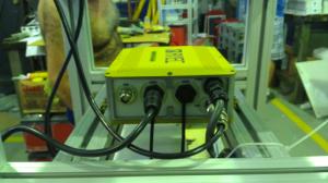
MS4580 Installation Description
Características:
1. Your AIS module provides precise positioning and operational information through its Ato n - Assist module for Type 1 Navigation
2. Low power consumption
3. Real-time information
4. IALA Recommendations and ITU Publications (ITU-R M. 1371-1)
5. Operates in the VHF Maritime Mobile band
Operation principle
System consisting of a Solar power pack that uses 4 panels, a Charge controller and a battery to capture, store and supply power to your AIS module and its signaling module (Flashlight MS451X).
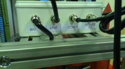
 Your Solar Power system is always in the active mode and through a general switch command, available on the outside, allows you to switch on or off the AIS modules and Signaling lantern.
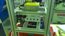
The modules are mounted on an anodized aluminum chassis and this is mounted on its lower mounting plate. This assembly allows a structure with robustness necessary to the solar assembly.
ATTENTION: The Charging Controller of the Solar Power System whenever it is first plugged into your battery takes about 10 minutes to release the use of your charge.
The model used has a numeric display which indicates its internal working configuration, in this application it should always be indicating "00" so that the system remains constantly "on", if it is necessary to change this value, it can be done by pressing " Press the on/off button (power) for 5 seconds, then select the desired option and then wait to stop blinking to confirm the change. Whenever the same undergoes a change of configuration or is connected to your battery we remind you to wait for about 10 minutes for the controller to turn on its charge.
Its AIS - Automated Identification System module provides its position through an internal GPS of 50 channels and accuracy with a maximum error of 2.5 meters. It uses an appropriate antenna located at the top of the set and transmits this information (and more optional information on battery voltage, weather, etc.) through your VHF antenna, also located at the top of the set.
Specifications
Supports Messaging 21,6,7,8,12,13,14,25 depending on hardware and software equipped
Supports messages of Meteorology and Hydrology (Message 8)
Supports synthetic and virtual AIS AtoN
Total compatibility IALA, IEC, and standard ITU
Settings Access:
AIS
Type 1 AIS module (equipped with a VHF transmitter only) must initially be configured through its available serial port on the bottom of the module, using an appropriate cable (MIKE-3P to DB9), supplied with the COM , For connection to a PC unit. It is necessary to perform this configuration only once to enable the messages from your AIS. The configuration procedures for your AIS are available in attached documentation and / or media according to the AIS model of your set. (MS4580-AIS Altamira Technology or MANDO-301 AMEC).
Flashlight
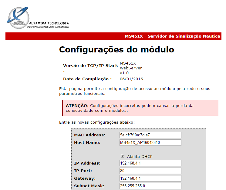
The Flashlight can be configured by any portable unit that uses a Wifi interface and has a Browser, Chrome, for example. The Flashlight MS451X is a Web Server and generates its own access page for configuration and through this page you can configure all the parameters available in your model. The Wifi Access to your Flashlight is protected by encrypted access password.
After connecting to the Lanterna through its Wifi access we can access its configuration page, through a browser, through the default address "192.168.4.1".
Please wait a while to load the configuration page as it can be seen on the side.
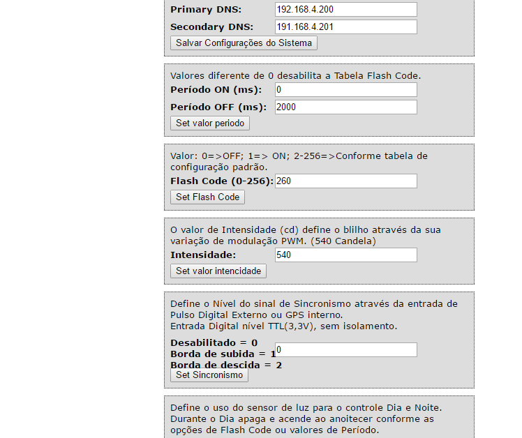
Through this page we can define:
On/Off
Periods Flash Code
Intensity in Candles (cd)
Set synchronism signal (Rising or Descending Edge)
Defines the use of the light sensor (Day/Night)
Access page view for setup

Installation
The MS4580 module when removed from its box through "eyebolts" (not supplied) attached to the top of the assembly and observing the utmost care with its Flashlight installed in the upper center, will already be equipped with its GPS Antenna and it is necessary to fix its VHF Antenna which is supplied in separate packaging.
VHF Antenna Installation
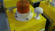 Attention: The VHF Antenna is attached to the top of the set opposite the GPS Antenna. The VHF connector that is available and attached to the top of the assembly must be used, making sure that it does not fall into the MS4580 assembly, and then attaching the VHF Antenna body to the available bracket, attaching the VHF antenna through its side screw in the bracket body
When finalizing the installation of the GPS Antenna the module is ready for use, simply connect it through its general switch located at the bottom of the module.

Then a PC unit must be connected through its serial cable (supplied) to the initial configuration of the AIS unit. Setup procedures are available in documentation provided on digital media along with the unit.
 For the configuration of functioning of the model of Lantern equipped simply access it through a unit that has a Wifi link and a browser. Configuration possibilities will be available on your "htm" page.
Request your password!
Opening the set
In order to perform any maintenance, care should be taken when lifting the casing of the assembly as some cables are of sufficient length for their connection, so when "hoisting" the casing of the assembly we must raise it to a sufficient height that allows to disconnect the cables of the Solar panels (they do not have order of placement) and then you can raise it a little more to remove the cables of the GPS Antenna, VHF and Flashlight . The other cables interconnect the internal drives.
Lower Mounting Base Plate Detail
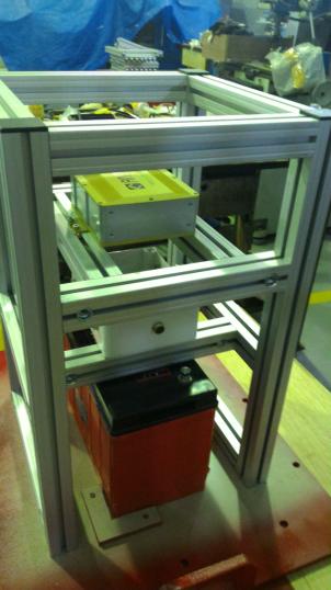
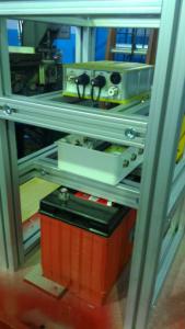
The Lower Mounting Plate is an integral part of the module, because it is where the aluminum chassis and the Solar Power System battery are mounted.
Fixing the float
The fixation in buoys was arranged in this Lower Mounting Plate where we find 4 reserved through holes for this, which allow the fixation in your float destination as can be seen in diagram below and in the image to the right:
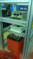
Fixing Battery
In the picture we can see the battery that is locked in its base of inferior assembly and also locked by the aluminum structure of the chassis, to remove it it is necessary to use an Allen wrench in the connector of the bar of the aluminum structure just above the battery.
ATTENTION: The measures described in this document may vary between modules of the same lot!
Detail of Top Mount Base Plate

For Information and Prices Contact Us